

1、 All functional parts of the terminal
Description of each functional part of the terminal
1. The locking device of the self-locking terminal in the sheath. The self-locking terminal of the conventional terminal generally has three positions, the front side of the terminal, the rear side of the terminal and the two sides of the terminal, which are used to fix the terminal in the sheath to prevent the terminal from giving way (falling out of the sheath).
2. The contact area between the wire conductor and the terminal in the core crimping area, through which the current and signal are transmitted between the terminal and the wire and the electrical appliance. At the same time, it is also an important field to ensure electrical and mechanical properties.
3. The contact area between the wire insulation layer and the terminal in the insulation crimping area has two functions:
(1) To prevent the conductor core from being exposed at the end of the sheath due to the contraction of the conductor insulation layer, and the arc connection short circuit will occur under high voltage;
(2) After the end of the terminal in the insulation crimping area contacts with the winding wire, the swing amplitude between the wire and the terminal shall be limited to prevent the possibility of wire core fracture caused by excessive swing.
4. When the end of the fixed guide rail is installed in the jacket, the main functions of the fixed guide rail are as follows:
(1) When the terminal enters the sheath, it plays a guiding role;
(2) After the terminal is installed in the sheath, it can fix the terminal, so that the terminal cannot rotate or swing left and right in the sheath, so as to ensure the assemblability and stability of the terminal, terminal and sheath.
5. During the cold stamping connection of the strip cut-off point terminal, press the die to separate the terminal from the strip.
6. The front and rear protective openings are the bumps left after extrusion deformation during crimping, and protect the core in the crimping area from damage during cold stamping connection.
7. After the crimped lead is connected with the terminal by cold stamping, the lead core in front of the front protective opening is the lead core in the transition zone.
8. The buffer transition zone is the area between the core crimping area and the insulation crimping area during the stamping connection, which is mainly used as the area causing deformation and stress diffusion during the cold stamping connection.
2、 Terminal each functional area
The functional areas of terminals are different in three different self-locking positions.
1. Crimping area The area where the terminal completely contacts the wire is the extrusion deformation area of the die on the terminal during practical application, including the core crimping area and the insulation crimping area.
2. The transition area between the crimping area and the bonding area or between the crimping area and the self-locking area is mainly used for the connection, transition, and placement of the crimping head.
3. Self-locking area The area where the terminal self-locking is located, that is, the area used for the fixed locking between the terminal and the sheath.
4. Connector area The area where the male terminal and the female terminal fully contact when they are installed together to transmit current or signal.
3、 Important control parameters in terminal cold stamping connection
1、Length of crimping head
The length of terminal crimping head has a serious impact on the performance of terminal crimping connection. In practical application, two requirements must be met:
(1) The crimping head is visible. Only when the crimping head is visible can the pull-out force of the terminal after crimping be more effectively guaranteed and the mechanical performance be met;
(2) The crimping head shall not extend into the bonding area and self-locking area of the terminal, otherwise it will affect the assembly performance of the terminal and the sheath, make the terminal unable to fit into the sheath normally, and affect the ideal contact between the male and female terminals, and sometimes lead to incomplete assembly and locking between the mating sheath. The value of crimp length is determined by the characteristics of the terminal itself. Different specifications of terminals have different requirements for the value of crimp length, and terminals designed by different manufacturers have different requirements for the length of crimp. The length of the crimp joint of the terminal is determined by considering the specification of the terminal. When the small size terminal is matched with the small size wire, the length of the crimp joint is shorter, and when the large size terminal is matched with the large size wire, the length of the crimp joint is longer. For example, some traditional terminals have different requirements on the length of crimping lead due to different manufacturers and users.
1) MOLEX requires that the length of crimping head should be 1 time of the visible outer diameter of the wire core, and should not extend to the bonding area at most.
2) DELPHI requires that the length of terminal crimping head be more than 1mm.
3) YAZAKI requires the length of terminal crimping head to be 0.1~1.0 mm.
4) AMP requires that the crimp length of terminals is 0.5~1.0mm, and that of some more precise terminals is 0.13~0.51 mm.
5) KET requires that the length of terminal crimping head is 0~2.0 mm.
6) JST requires that the head length must be visible.
7) Some Japanese-funded enterprises set the length of compression joint at 0.5~1.5 mm.
In general, the above values are only a conventional specification. For some special terminals, they need to be determined according to the terminal application. For example, the 81PIN model of the engine ECU of Great Wall Spirit and other vehicles is the 928999-1 terminal in the 368290~l sheath. The crimping head must be controlled at 0~0.5 mm. When this value exceeds 0.5 mm, it may be difficult to insert the self-locking strip; After the self-locking strip is installed in the sheath, the short circuit of wire core connection occurs in the adjacent holes.
2、Visibility of wire core and insulation layer
The position of the wire core and insulation layer in the buffer zone is one of the important factors in the cold stamping connection process of the terminal. The wire core and insulation layer must be visible in this area. Cold stamping connection requires that the exposed length of the buffer transition zone core and insulation layer is equal, but it is difficult to do this in practical application, but both must be visible at the same time. When the wire core is not visible in this area, it means that the insulation layer of the wire is pressed into the crimping area of the wire core, resulting in the reduction of electrical performance after crimping; When the insulation layer in this area is not visible, it means that the insulation layer of the wire is not properly pressed by the terminal, and the wire core is out of protection. During use, the wire core may break, leading to the decline of electrical performance. In serious cases, safety accidents may occur. The following examples are used to analyze the requirements of different manufacturers and users for general terminal parameters. Some Japanese-funded enterprises stipulate that the location parameters of the wire core and insulation layer in the transition zone are: the size of the wire peeling port and the port before the terminal insulation crimping zone is 0~1mm.
MOLEX, DELPHI, YAZAKI, AMP, KET, JST require that the conductor insulation layer and conductor core between the insulation layer and the core crimping area must be visible.
3、Cutting length of material belt
During cold stamping connection of terminals, the length between the rear end of the terminal insulation crimping area and the cutting point of the strip or the length between the front end of the terminal and the cutting point of the front strip is the cutting length of the strip. In the process of cold stamping connection and crimping, when the terminal is cut off from the strip, if the remaining tail material is too long or too short, it will lead to three adverse consequences:
(1) After the terminal is inserted into the sheath, the long metal tailings will extend to the rear end of the sheath, and the high voltage will cause the arc between the adjacent contacts of the connector;
(2) If the material at the front end and tail of the terminal is too long, it will interfere with the connection between the terminal and the sheath, terminal and terminal;
(3) When the cutting length of the strip at the front and rear of the terminal is kept very small or even invisible, the terminal may be cut, resulting in the terminal cannot be used. The following manufacturers have different requirements for the strip cutting length of traditional terminals.
1) DELPHI stipulates that the front cutting strip must be visible, and the cutting length of the rear cutting strip must be visible with a maximum of 0.5 mm.
2) AMP stipulates that the cutting length of the rear end strip of terminals 250 and 070 must be visible, and the maximum length is 0.25 mm.
3) YAZAKI stipulates that the cutting length of the rear end strip is 0~0.3 mm, and the maximum is not more than 0.5 mm.
4) The maximum cutting length of the front and rear strip shall not exceed 0.5mm according to the regulations of KET.
5) MOLEX stipulates that the cutting length of the front and rear strip is about 1~1.5 times the thickness of the terminal material.
Generally speaking, the cutting length of the front and rear material strips must be visible, which can not affect the assemblability of the terminal at most, and the tail material strips can not extend out of the sheath tail.

Manufacturer of on-board harness, new energy charging pile harness, terminal harness, vehicle OBD2 diagnostic cable, LVDS harness
Copyright: Shenzhen Robust Electronics Co., Ltd


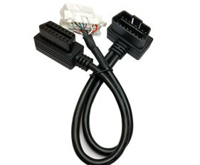 OBD16P male to OBD16P female + Toyota 16P female
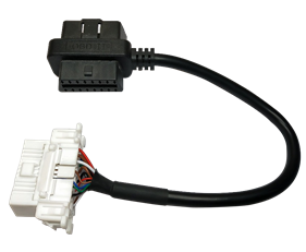 OBD16P male to female adapter TO Toyota 16P female
 FFC flexible cable OEM
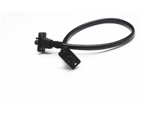 HSD4+2 waterproof wiring harness
 HSD4+2 waterproof adapter cable