

1、 Automotive wiring harness - definition
The power supply and various electrical components on the vehicle are physically connected through the wiring harness, which is distributed throughout the vehicle.
If the engine is compared to the heart of the car, then the harness is the neural network system of the car. It is responsible for the information transmission between the electrical parts of the whole vehicle.
2、 Automobile wiring harness · design process
1. Determine the electrical functions of the whole vehicle and give corresponding requirements.
2. Determine the electrical load requirements of the whole vehicle and give relevant special requirements.
3. Draw the electrical schematic diagram and circuit schematic diagram of the whole vehicle.
4. Vehicle allocation (including tower line).
5. Determine the wire specification, wire protection, fixation and through-hole mode.
6. Distribute the circuits contained in the protection device and determine the capacity one by one.
7. Draw a 3D harness layout.
8. Draw a 2D harness diagram.
9. Use the 3D harness layout to confirm the size of the 2D harness diagram.
10. Obtain approval and put into production.
1) The two power supplies (generator and battery) equipped on the vehicle must be connected in parallel;
2) All kinds of electrical equipment are connected in parallel and controlled by their own switches;
3) The ammeter must be able to detect the charging and discharging current of the battery. Therefore, when the battery supplies power, the current must pass through the circuit composed of ammeter and battery. However, the exception is that the starter current consumption is large and the working time is short, that is, the starting current does not pass through the ammeter;
4) All types of cars are equipped with safety devices to prevent short circuit and burning of electrical equipment.
3、 Car harness · design points
1. Draw electrical schematic diagram and harness function diagram according to electrical function requirements.
2. According to the electrical schematic diagram, distribute energy for each electrical subsystem and circuit, including tower iron line.
3. Determine the wiring form of the harness according to the distribution of electrical components in the electrical subsystem.
4. Determine the harness protection mode and through-hole protection according to the harness direction.
5. Determine the fuse or circuit breaker according to the electrical load.
6. Determine the wire diameter according to the fuse capacity.
7. Determine the color of the wire according to the function of the appliance.
8. Determine the connector of harness according to the connector of electrical equipment.
4、 Car harness and wire setting
1. Calculate wire diameter
I=P/U
A=IpL/Ud
Where:
1: Current, A
P: Power of electrical parts, W
U: Voltage, V
A: Wire diameter, mm ²
p: Copper resistivity (about 0.0185 Ω mm ²/ m)
50: Conductor length, m
Ud: maximum allowable voltage drop loss
Also consider the following:
A. If the wire is too long, the wire diameter can be appropriately increased;
B. If the wire is connected to the electrical appliance after transmission through multiple connectors, the wire diameter can be appropriately expanded considering the large voltage drop at the terminal.
2. Allowable voltage drop Ud of various circuits
3. Empirical value of wire diameter
0.5mm ² Signal line, tail light, license plate light, indicator light, instrument light, clock, water temperature gauge, fuel gauge, oil pressure gauge, etc.
0.75mm ² Turn signal, electric horn below 3V, etc.
1.0mm ² Electric horn, wiper motor, fog lamp, etc.
1.5mm ² Headlamps.
2.0-4.0mm ² Power cord
4.0-6.0mm ² Glow plugs, etc.
8.0-25mm ² Main power supply.
16-72mm ² Start line, main tower iron line.
4. Wire color setting
Main power supply: red
Starting system (ignition): white
Grounding system: black (white and black)
Signal light system: green
Sensor signal: brown, yellow
5. Allowable continuous current and allowable current density of conductor
In order to avoid excessive heating of the conductor, the current density should be checked, and its formula is: S=I/A.
5、 Car harness and electrical wiring
1. Starter
Starter fault analysis (cause of no rotation):
① Insufficient battery capacity
② Poor wire connection.
③ Start switch (relay disconnected)
④ The starter is broken.
Check and eliminate:
1. Turn on the starter switch. When the starter does not turn, immediately release the switch, turn on the headlight or press the horn to confirm whether there is power. If the headlight does not light or the horn does not sound, check the connection status and battery capacity of the battery circuit.
2. If the battery is normal, use a wire or screwdriver to directly lap the terminal of the starter switch. If the starter is idling well, it means there is a problem with the switch. Otherwise, there is a problem with the starter.
3. Check the starting relay in the same way as above, and directly short the two wires of the relay coil with a screwdriver.
2. Generator
3. Brake light, reversing light
Fault analysis of brake lamp (reversing lamp) (cause of failure):
① The bulb is burnt out.
② The bulb tower iron does not light.
③ The switch is damaged.
④ The line is open.
Inspection and troubleshooting
① Check the bulb filament.
② Check tower iron: press the brake pedal and check whether the brake lamp is powered on.
③ Check the switch. If it is still not connected, it means that the circuit is open or the fuse is broken.
4. Electric/pneumatic horn (high and low beam conversion)
Electric horn does not sound
① Power line broken
② Poor contact of button
③ The relay is broken
④ The horn is broken
Inspection and troubleshooting
① Turn on the headlight and confirm that the battery capacity and power circuit are normal through the lighting status of the headlight.
② Short the horn relay terminal 30 and 87, and the horn will sound normally. Change the horn if it doesn't sound.
③ Tower the 85 terminal of the horn relay. If the relay contacts close and the horn sounds, the button is normal.
④ When the button is pressed, the relay has no sound. Replace the relay.
5. Radio player
6. Interior light
1. Turn on the front fog lamp before turning on the rear fog lamp.
2. When the front fog lamp or headlamp is turned on, the small lamp switch will be turned on at the same time.
3. The small light, license plate light, tail light, instrument lighting and rocker switch indicator light are the same power supply, but the instrument lighting and rocker switch indicator light are controlled by the lighting controller.

Manufacturer of on-board harness, new energy charging pile harness, terminal harness, vehicle OBD2 diagnostic cable, LVDS harness
Copyright: Shenzhen Robust Electronics Co., Ltd


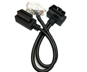 OBD16P male to OBD16P female + Toyota 16P female
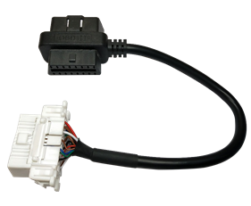 OBD16P male to female adapter TO Toyota 16P female
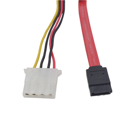 FFC flexible cable OEM
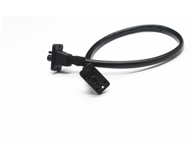 HSD4+2 waterproof wiring harness
 HSD4+2 waterproof adapter cable