

1. Check whether the crimping die is clean and worn. Clean and replace worn dies if necessary.
2. Disconnect the power supply of the crimper and remove the protective device.
3. Install the corresponding mold.
4. Load the terminal into the mold so that the first terminal is above the anvil.
5. Manually cycle the crimping machine to complete a complete crimping cycle to ensure the smooth crimping process. If it is not smooth, take out the mold and check the closing height. Go to step 3.
6. Check whether the mold is aligned. Check the indentation of the anvil at the bottom of the terminal. Check whether the extrusion part is symmetrical and the crimping part is centered. If the asymmetry is not centered, align the tool and then go to step 5.
7. Check whether the terminal feeding device feeds the next terminal directly above the anvil. If not, please adjust the terminal feeding device and feeding head and go to step 5.
8. Replace all previously removed protective devices. (Observe all safety regulations listed in the crimping machine and/or crimping tool manual).
9. Electric crimping terminal sample.
10. Evaluate the tail cutting length and bell mouth of the core wire press frame. If adjustment is necessary, disconnect the power supply of the crimper and remove the protective device. Adjust the track position. Manually cycle the crimper, check the feeding position of the feeding finger, and enter step 7.
11. Evaluate the conductor brush. If adjustment is necessary, disconnect the power supply of the crimper and remove the protective device. Adjust the wire stop on the crimping workbench or the crimping position of automatic wire processing equipment. Go to step 8.
12. Check the position of the insulation sheath. If necessary, adjust the stripping length, crimp the new sample, and then go to step 11.
13. Adjust the height of the insulation skin crimping so that the insulation skin crimping does not contact the wire core.
14. Crimp the terminal sample.
15. Measure the crimping height of the core wire (if applicable) and compare it with the specification. If necessary, cut off the power supply and remove the protective device. Adjust the crimping height of the core wire, replace the protective device, connect the power supply, and then go to step 14.
16. Perform tensile test. If the test fails, refer to the troubleshooting instructions.
17. Adjust the crimping of insulation sheath.
18. Crimp the terminal sample.
19. Evaluate insulation crimping. If necessary, cut off the power supply and remove the protective device. Adjust the crimping height of the insulation sheath, install the protective device back, connect the power supply, and then go to step 18.
20. Measure the crimping height and compare it with the specification. If necessary, cut off the power supply and remove the protective device. Adjust the crimping height of the core wire, replace the protective device, connect the power supply, and then go to step 18.
21. Record the measurement results.
tensile test
1. Cut the wire into a length of about 150 mm.
2. Peel off the insulation skin at one end, the extent of peeling is 13mm or long enough to make the insulation skin not under the insulation clamp, or loosen the crimping of the insulation skin to make it have no grip on the insulation skin.
3. Crimp the corresponding terminal to the wire according to the rated crimping height.
4. Visually inspect the bell mouth, conductor brush and cutting core wire.
5. Set the tension tester to 25.4 mm per minute. For most applications, faster speeds do not have a significant impact on data. The slower speed can prevent sudden force or jerk from breaking the core wire.
6. If necessary, tie a knot at the end of the wire not connected to the terminal (if the insulation sheath slides on the core wire).
7. When using a tensile tester for testing, the wires and terminals must be clamped. (Note: during the test, clamp the terminal plug interface instead of the crimped part of the core wire).
8. Conduct tensile test.
9. The intelligent tension tester can automatically record the tension reading. For each crimping operation setting, at least five tensile tests shall be conducted and at least 25 readings shall be taken to determine the capacity of the process.
10. Compare the minimum reading with the specified minimum tensile strength.
Note: When two wires are crimped together, large deviation and low process capacity index value often occur.
The increase of this deviation is due to the increase of conductor brush deviation and conductor bell mouth deviation, as well as the decrease of the number of core wires on a set of core wire harness that can contact the sawtooth of the terminal connection frame.
The industry believes that the crimping of double conductors is not better than the crimping of the thinnest conductor.
① If you grip two wires and pull at the same time, the pull reading is higher.
② If only one wire is pulled, the tension reading will be much lower.
③ If the thickness of the two wires is the same, the tension value of the upper wire is lower than that of the lower wire, which is due to the bite effect of the terminal teeth.
Measurement of crimping height
1. Complete the tool setting step by step.
2. Crimp at least 5 samples.
3. Clamp the flat blade of the crimping micrometer to the double radius center of the core crimping frame. Do not measure near the bell mouth of the core crimping frame.
4. Rotate the dial of the micrometer until the measuring head contacts the bottom radial (curved) surface. If using calipers, make sure that the crimp extrusion is not measured.
5. Record the crimping height reading. At least five crimp height readings should be taken to confirm each setting. At least 25 readings are required to determine the process capacity.
6. During the crimping operation, the crimping height should be checked every 250 to 500 terminals crimped.
Note: The crimp height is usually drawn as a control icon, because the crimp height measurement is a fast non-destructive measurement, which is very important for the electrical and mechanical reliability of the terminal.
There are three main purposes for drawing control charts.
① The number of samples collected for setting is usually small, so its statistical value is limited.
② The occurrence of special circumstances that may cause consequences in the process is irregular and unpredictable, and there must be means to record the deviation in time. This can prevent thousands of termination fittings from being scrapped after operation.
③ It is important that the data is necessary to evaluate and improve the crimping process.

Manufacturer of on-board harness, new energy charging pile harness, terminal harness, vehicle OBD2 diagnostic cable, LVDS harness
Copyright: Shenzhen Robust Electronics Co., Ltd


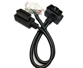 OBD16P male to OBD16P female + Toyota 16P female
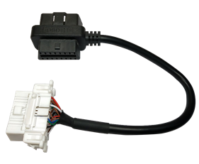 OBD16P male to female adapter TO Toyota 16P female
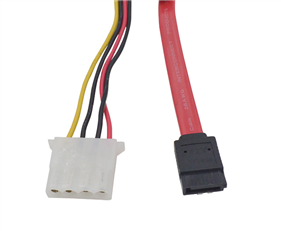 FFC flexible cable OEM
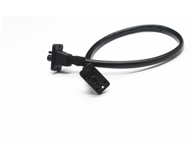 HSD4+2 waterproof wiring harness
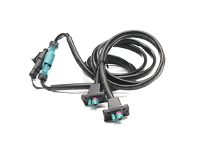 HSD4+2 waterproof adapter cable